 That remains the question. The Microchip PIC line of processors is widely available in all kinds of varieties. For
every application, there is a PIC. This is a great strength but also a weak point. For every OTHER application you
need to learn yet another PIC chip.
That remains the question. The Microchip PIC line of processors is widely available in all kinds of varieties. For
every application, there is a PIC. This is a great strength but also a weak point. For every OTHER application you
need to learn yet another PIC chip.
Still, the PIC's are good processors and there are a lot of cheap programmers available for it.
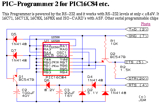
One of these programmers is the JDM programmer, designed by Jens D Madsen. Please visit his website at
www.jdm.homepage.dk
and read all about the hardware and the associated software. On the right, you see his original design and the
original circuit drawing.
Among the members of the WISclub, the JDM programmer is a returning topic. So after todays revisit of the JDM
hardware I felt forced to dig into the design and see if I can understand it or not.
 To the left is the circuit of the first generation JDM hardware. It is easier to understand since the main
capacitor (for the Vpp generation) is coupled without a separate transistor. But in essence, the circuits are
comparable at least.
To the left is the circuit of the first generation JDM hardware. It is easier to understand since the main
capacitor (for the Vpp generation) is coupled without a separate transistor. But in essence, the circuits are
comparable at least.
If TxD goes -9 Volt, C1 and C2 are charged to 9 Volts. Due to D2, C2 does not charge higher than 5.1 Volts. When
TxD goes positive to +9 Volts, the already present 9 Volts stored in C1 are pushed up another 9 Volts so that C1
now holds 18 Volts. But D1 brings it down to 13 Volts.
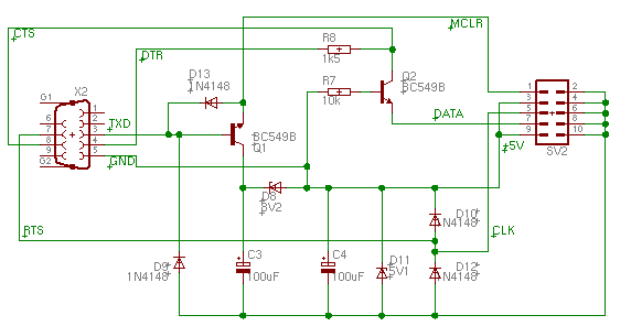
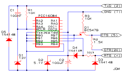
I took the liberty to redraw the above circuit with the PADS software. In the drawing above, you see the
result. I think this is somewhat easier to read than the original drawing. What happens in the JDM programmer
is the following:
- Bringing RTS positive charges C2 to 5 Volts and C1 to approximately 13 Volts
- By bringing RTS negative, the voltages on the capacitors are increased
- The PIC ground level is floating at 5.1 Volts below RS 232 signal ground
- When TXD goes positive, it opens up Q1, so the 13 Volts goes to the Vpp pin of the PIC (/MCLR)
- By manipulating RTS and DTR (for RB6 and RB7), data is pumped in and out of the PIC
-
The situation around RB7 is rather complex. The rule seems to be: CTS = DTR unless RB7 is ZERO.
Or, in Modula-2:
IF RB7=High THEN CTS:=DTR ELSE CTS:=RB7 END;
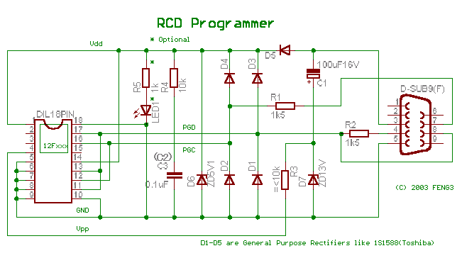
Above is the design of the RCD programmer. It can be found at the site of Feng3 (Three is pronounced 'san' in
Japanese so it should be Feng San which translates to Grandmaster Feng):
https://feng3.cool.ne.jp/en/rcd.html
Oh Feng charges his main capacitor in the negative TxD phase and when he turns TxD positive, the voltage is roughly
doubled so this design will work with laptops and similar which have +/- 7 Volts RS 232 levels.
Operation is rather straightforward. But Feng took better care of protecting RB6 and RB7 by means of the diodes D1
.. D4. RB7 feedback is done without a transistor. It seems to work. This would be my preferred design, to be
honest.
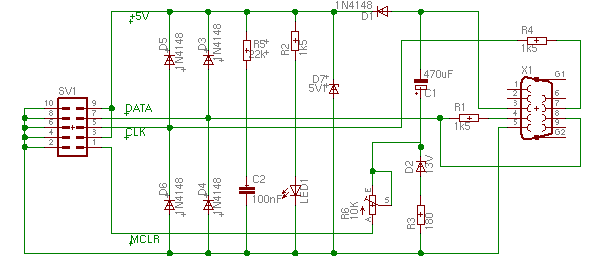
This is one of the latest versions of the RCD programmer by Feng San. It is better for programming the newer
PIC chips since these require the Vpp to come up before the Vdd comes up. Feng San solved this with an RC
delay line. Very convenient.
I took the liberty to redraw the circuit in EAGLE.
 To the left, you see a female bodybuilder. You can see this is a woman since she wears a bikini top. I cut off
the head for privacy reasons. Do you see that body? The tone of the muscles? See anything else? Neither do I.
It's a pity.
To the left, you see a female bodybuilder. You can see this is a woman since she wears a bikini top. I cut off
the head for privacy reasons. Do you see that body? The tone of the muscles? See anything else? Neither do I.
It's a pity.
The JDM programmer is like a female athlete. Her body is trained to do just the one sport she prefers. Muscles
and bones. Not more. Not even femininity. A dedicated machine that's hard to improve. Sometimes nice to look
at, but not always. Do you like to see the female bodybuilders or (even worse) weightlifters? I don't. I want
to see some fat, here and particularly there. Curves, instead of lines.
Same with the JDM programmer: you cannot make improvements by means of simple modifications. The JDM's are
built to perform, stressing its components to the limits. No fat added.
I took the liberty to add some fat to the JDM programmer: ImJDM was born. More about that in the related file.
 I may have some doubts about the JDM programmer, people still use it, so it must be good. And why throw away
something that's good? It doesn't make sense.
I may have some doubts about the JDM programmer, people still use it, so it must be good. And why throw away
something that's good? It doesn't make sense.
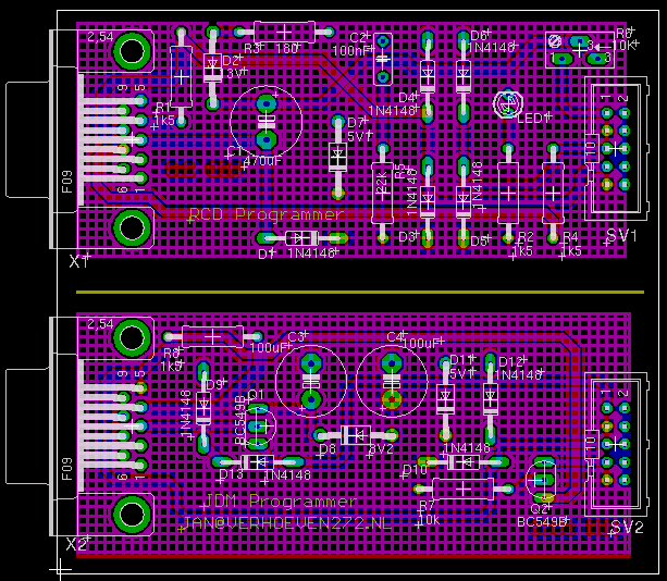
So I decided to have a professional PCB company make some double sided PCB's. One board contains the tracks
for an RCS 2.3 and a JDM 2. The prices are:
- RCD board only : €4
- JDM board only : €4
- RCS + JDM board on one panel : €5
- worldwide shipping €1
If this appeals to you, place your order now, using the PayPal button below.
The board ends in a 10 pin ribbon cable connector. So you need to make one or more for each programmer socket
you want. I think this is more versatile. The 10 pin connectors on both boards (JDM and RCD) have the same
pinout so you can use them on either board.